As shown here, the heliostat targets an optical prism to divide the spectrum of light as a light fraction demonstration (Energiegarten Siegen/Westf.).

Photo 96
At the left side you can see the Heliostat of EGIS. It targets the sun light upon an optical prism (in the middle of the photo). The sun light is devided into its spectral colours and send from there to the solarpavillon (at the right side).
Photo 97 Photo 98
Heliostat spectral colours of the sun light
Equipment Gesellschaft für Internationale Elektronik Systeme
Select Language: German - English
EGIS-Logo Back to the homepage Photo 80

SolarTracker

Bi-Axial-Sun-Tracking-System
Photo 80
      CONTENT:   versions | extensions/options | system description | specifications | price list     
      IMAGES:   gear parts and options ||   MORE IMAGES AND INFO       


  • Energy gathering out of an inexhaustible reserve. Deflect energy. Concentrate energy in focus. Collect energy without cost collects over years – easier, more comfortable, more effective! And increasing energy (comparison between yield & power).
  • Get knowledge and recognize the sun in science, research and education by precise positioning, and easy & comfortable probe tracking!
  • Get natural light – sunlight – into the house, at the job, during doing handicrafts and hobby. Sunlight on the northern side of the house! Point-exact, the whole day over. Natural sunlight for heat, energy, health, cosmetics and fitness. Using sun the whole year long!

    The SolarTracker, the positioning and tracking system made by EGIS offers this and still some more!


Photo 95 The SolarTracker at the en-
gineer school St. Imier (EISI)
in Switzerland. It works at the
"Mont Soleil" in the biggest
PV experimental field of
Switzerland and positions the
"Sun Spot Conzentration
System" of the Midway Labs,
USA.
Photo 160 You can see it right now: at the University
of Nottingham/UK light plays an important
role. Here the SolarTracker positions a
fresnel lens enabling collection of the light
by the optical fibre bundle.
Photo 131 The EGIS SolarTracker at the Solar Research
Institute CIEMAT (Spanish Public Center for
Research on Energetical and Environmental
Technologies) in Spain. Clearly the function of
the panel carrier is noticeable. Here it is holding
and positioning diverse sensors for measuring of
irradiation, brightness and colours of the sun.
Photo 123 EGIS SolarTracker
as mobile unit used
for measurement of
solar panels at the
"Netherlands Energy
Research Foundation"
ECN (Netherlands)


A system – approved since more than a decade in heavy duty (image J & image K) – consisting out of an outdoor and an indoor unit:

  • The outdoor unit contains a swing/tilt rotor with the possibility of mounting a big mirror/reflector/panels. The rotor has two electro-motors and can turn the rotor-head with reflector/solarpanel horizontally 180° – it's vertical lift range amounts 68°.

    According to the wind-strengths to be expected an utilization-S-surface up to 6 sqm can be operated. The balanced static load should not exceed 50 – 85 kg. Between the control box and the rotor spacing up to 200 m is allowed.

  • The indoor unit consists out of a complete computer with rotor power supply. These electronics are established in a metal casing with front sided operating elements and a 40 digit LC-Display. On the rear you will find the connection-clamps for the cable serving the rotor and the connectors for RS 232 C-Interface and analog input.

    Into control box (indoor unit) of the equipment the geographical location of the rotor has to be input in longitude and latitude via a key-field. Out of these statements and with the time of the year and the day (learnt from the internal electronic calendar with clock) the processor calculates the exact sun-position. Now line up, using the front sided keys of control box, to approach the exact sun-position in optimum. Ready!
    From now on it is tracked automatically, timely exact and synchronous to the daily sun-sprint – within the physical possibilities. Also leap-years are regarded!

    Position corrections can be easily inputted via 4 keys (higher – lower – left – right).


The usage of the positioning system could be divided into two function areas:

  • Direct and synchronous sun tracking and path following. The rotor and thereby the rotor head mounted object (solar collectors, photovoltaik-panels, parabolic or spherical reflector, radio probe etc.) is directly looking into the sun. This Direct-Tracking can be managed with this system without any problem.
    The spherical utilization cone covers 90° to 270° in azimuth at an elevation span of 68°. Whereby the EL-span location freely can be determined by the user at the site. Usable are e. g. 0° to 68° or e. g. 25° to 90° or all positions between that with a span of 68°. With optional order "AZ360" a full 360° horizontal turn angle is available.
    Typical operational field: increase in yield and performance towards fixed panel/collector (comparison between yield & power).

  • Sun light deflection with a flat mirror (following optical principle light in angle equals light out angle) onto any wanted point. The mirror mounted on the rotor head automatically is driven into a position exactly between sun position and light goalpoint, and thereby sunlight automatically gets onto the wanted point (within physical restrictions) whole day long.
    This Indirect-Tracking following the principle of Heliostat can be achieved easily too. At Indirect-Tracking the rotor at any time can deflect all sun positions between 90° east to 270° west onto any desired goal within these limits, if it is allowed by the location and magnitude of the elevation swing. All further sun positions resp. from north (0°) to east (90°) and from west (270°) to north (360°) can be utilized however within a restricted goal angle. Indirect Tracking (Heliostat function) is available in version "SolarTracker Pro" only in combination with the extension "MotionControl".


Important information: The accuracy of the system is so high that under favourable conditions distances of up to 200 m between mirror and goalpoint are achievable!

Complete, ready Heliostat systems you can find at Heliostat (www.egis.eu/Helio_us.html).


Photo 42 Heliostat with 4 m2 mirror
serving for illumination
of a north oriented winter
garden
Photo 127 An interesting installation in
Kopenhagen/Dänemark: The
four Siemens-PV-moduls are
diagonally arranged and are
carried by a fan-shaped frame.
Photo 8 Rotor with 90° head for astronomic
application. Azimuth rotating axis is
mounted parallel to the earth's axis.
(Radio-astronomic Department
"German Museum", Munich – Photo
Reg. Nr. R3665/17).
Photo 118 EGIS-rotor in comparison
with other solar-panel-
tracking systems


VERSIONS back to the beginning


Available in two basic versions:


O

Photo 49

Photo 48

Photo 14

SOLAR-TRACKER

consisting of of rotor and control box for the astronomical calculated tracking of objects conform to the sun-position, using Kepler data

  • 68° elevation span
  • 180° azimuth turn angle
  • intelligent control box
  • 40 digits LCD-display
  • lots of dynamic operational information on the display:
  • operational data
  • time (clock)
  • analog level available     
  • date
  • AZ-angle     
  • EL-angle     
  • directions of run
  • and more, and more…
  • quartz-stable calendar clock
  • programmable limit-angles
  • battery backup memories
  • auto start after blackout

Operated completely via frontsided pushbutton-field.

Functions in sequence: At the mechanical montage the rotor lines up only roughly in north/south direction. After going operational only two parameter are to be inputted: the geographical coordinates of the built-up site (length and width) and the time/date (GMT). The considerations of leap years, the calculation of the true local time and the sun coordinates are done full-automatically. A rearranging of the internal clock at the change from summer- to wintertime is not necessary.

Aiming the sun directly: The rotor will – more or less – look beside the sun (the goal) due to mechanical montage errors. With 4 keys (UP/DOWN/EAST/WEST) could be driven on the sun optimum now easily. Ready! The tracker now follows the sun day by day – full-automatically. If the sun leaves a your preset angle-area, the rotor waits in night-sleep-position up to the next day and begins the daily work in the right moment at the right position again.

The tracking behavior (tracking) can be influenced itself by selecting the allowable angle deviation and/or by time-axis selection of the next search cyclus, taking care of the motors.

Of course one could approach with such a system exquisitely any position manually: with a look on the display, heeding AZ and EL angles, steer up and down. Minimal step-size of 0.1°!

In this version the motors are fully switched by mechanical relays respectively and a hard blocking action results. At higher loads and masses this permanent hard blocking with "Stop & Go" degrades accuracy and lifetime of the motors and gears. In such cases you should prefer the "SolarTracker Pro".


O

Photo 49

Photo 11

Photo 14

option to extend
– controlpanel in 19" rack:

Photo 12

SOLAR-TRACKER PRO

Has all features like "SolarTracker", but it is using solid state relays (without mechanically actuated motor switches) to treat material with care at permanent focussing/tracking.

  • no contact-burnout, due to mechanically contactless switching
  • less noise due to absence of switching or cutoff sparks
  • smooth, silent control unit, because no parts are moving
  • cultivated two-speed-operation, because semiconductors are switched on and off in high frequency
  • more precisely, because different speeds can be driven with solid state switches
  • improved tracking behavior, because the positions can be targeted more precisely by "stopping" and "starting" with reduced speed
  • operates complete automatically, resumes operation automatically after power failure
  • incl. Heliostat function (reflection mode) – only in combination with the extension "MotionControl"
  • Integrated wind-sensor-interface. The wind-sensor-interface is provided to connect a pulse-output wind-anemometer with the 4-wire-interface. After setting "pulse per unit of time" of the wind-sensor and after reaching the wind-speed trigger preset by the user, the unit turns into a more streamlining position also preset by the user (but only within the rotor's range of motion). The delay-time in this position can be preset, too.

In this version the motors are soft-powered upwards in two steps and slow down in two steps. By this dampened acceleration of masses motor, gear and bearing are less stressed and less abrasion wear occurs. Accuracy and lifetime are kept for a longer time.
"True" soft-start and soft-stop is achieved only with this "MotionControl" extension. Herewith the acceleration can be defined stepless individually.

In addition this version allows the installation of the speed-controlling (SERVO-) hard- & firmware "MOTION CONTROL" and the mounting of the control unit into a 19"-rack plug-in unit "GR-19".

Working with mirrors (indirect tracking) select the reflection mode. By this you aim to the selected goal with 4 keys (UP/DOWN/EAST/WEST). The present goal-vector will be calculated and stored internally. After this start tracking, the sun-vector now will be converted in accordance with the physical laws of reflection right into the mirror-position that the reflex of the sun always meets the goal-point determined by you. This is also performed day by day – full-automatically.


DISPLAY-READOUT
  operation status   mode   time   activity   day cycle   azimuth angle   elevation angle  
               
  RUN   M   15:34:48   Go   S   AZ123.5   EL015.2  
CAUTION: Not all function are available on all versions and for each operating mode.


Photo 177 At the 'University of California' in
Merced/USA the EGIS SolarTracker
is used for concentrating daylight
onto commercial buildings.
Photo 179 The Institution for thermodynamics
and heat technology at the university
of Stuttgart/Germany is calibrating
'pyranometer' with this installation.
You can see the EGIS light direction
finding tube in operation at the left
margin of the mounting surface.
Photo 192 EGIS on Taiwan (China) at 'ITRI' (Industrial
Technology Research Institute in Hsinchu) –
a testing station for PV modules and solar
collectors


EXTENSIONS & OPTIONS back to the beginning


O

DC 12 V

Electronic voltage conversion from 12 V DC to 24 V DC. The SolarTracker can be operated between 12 V up to 20 V with this option.


O

ANALOG-INPUT

This hard and firmware allows to feed an extern analogous signal into the control box on the rear side (image G). This signal is processed with 8 bit solution (0 until 255) and serves to the automatic position-optimization.

Typical uses are:

  • a temperature dependent solar collector slaved control and/or optimization
  • charge and voltage dependent photovoltaik panel tracking and/or optimization
  • a light (lux) dependent position optimization of optical lenses/collectors
  • and many more!

The demanded DC voltage should be within the area between 0.2 until 12 Volt. The input impedance is around 250 kOhm. As well as positive indicated signals as well as reciprocal signals can be processed. The operational area of the measured signal can be adapted to the probe as well as in amplitude/slope as well as in setting zero (signal var. 0.1 V pos/neg). The sampling input clockrate is about 250 Hz!
By this procedure signal performance is achieved never managable by hand.
If wanted this signal values can be interrogated via the RS 232 C interface separately – or automatically/cyclically. By use of the keys of the control box an optimization process can be started anytime (or with the sequence of letters "FOCUS" via data-interface). The optimization and tracking behavior can be influenced motor-saving itself by programming of the admissible signal break level (threshold) by selection of the next test cyclus timing, by determination of the signal amplitudes and by determination of the search algorithm. The pluggable connection cable to the probe is inclusive in delivery.


O

Photo 13

DATA-INTERFACE

Both versions 'SolarTracker' and 'SolarTracker Pro' can be connected to an external computer for communication using a two way »RS 232 C data interface« (datastream: 8 bit/no parity/1 stop-bit/300 up to 76800 baud with/without hardware-handshake).
The direction determining information are given via "RS 232 C" interface into the rotor-control. Likewise in opposing direction information can be loaded out of operational status. The intelligent interface allows operation via phone modem too.
When working together with the option "analog-interpretation" the system can be used for the analog signal controlled aligning and tracking of probe signals e. g. weather balloons. The measuring directions and the analog power values are transfered via the data interface onto the external computer permanently!
The communication between control box and external computer is managed in a kind of BASIC language, by which only the simple 7 bit ASCIl mode is used.

Command syntax examples:

  • Turn azimuth-motor on 134.56°   –   "AZ = 134.56 [CR]"   or
  • Command computer elevation position   –   "EL = ? [CR]"
  • Using the instruction-word "FOCUS" automatically starts an focussing-run.
  • Using the instruction "RESULT", after each auto-focussing the automatic output of operational and performance data is induced, e. g. AZ- and EL-angle with corresponding fieldstrength. These can be transferred to a computer (as a protocol for instance), but also onto a printer directly! These data can be stored on the computer's hard disk in a file and can be used in any commercially available spreadsheet program (MS Excel etc.) or in data bases and can be displayed graphically without a special program!
    The version 'SolarTracker Pro' is inserting date and time into this data string additionally. See a sample of this data string here:
    Row-no.; day; date; time; tracking-channel; AZ-angle; EL-angle; AZ-motor-pulses; EL-motor-pulses; level of analog-channel 1; 3; 4 in the format as follows: 00000 Mon 11.12.98 15:23:44 01 00000 00000 00000 00000 00000 00000 00000.
    This data can be transferred to a modem also! Built-in filters allow a multi rotor operation at a single interface. (Not all applications have yet been discovered. What's your idea: …?)

Already with any simple terminal program commands and responds can be managed via modem and wire!

This interface is needed to extend with the "GPS CAPTURE".


O

GPS CAPTURE FUNCTION   (only in combination with Data-Interface)

By this function you may take over global positioning data automatically from a GPS navigator/receiver via the serial interface into program-memory PRG 01 of the control unit.

The NMEA183 protocol with data set "GPRMC" will be used.


O

MOTION CONTROL   (only for SolarTracker Pro)

Hard- and firmware extension for the dynamic, controlled, dialog-oriented speed determination. You can select start acceleration, speed of silent service, maximum speed and break delay with high resolution. Especially meaningful for fine positioning and focussing of big objects/loads. Because of Soft-Start and Soft-Stop motor, gear and baerings are protected and positioning accuracy is longer preserved and the lifespan is extended. This extension is needed for usage of the 'Heliostat' function (indirect tracking).


O

AZ 360

Extension for 360° endless turnaround. This mech. gear option contains additionally reduced gear tolerances. It includes also extended firmware: it contains as well as widened on 360° oriented angle calculations as also a turn counter with programmable limit (to prevent cable damage). This limit is settable between 1 until 99 revolutions in each run-direction and is managed automatically.


O

SPEED

Speed improvement up to about 4-times of the standard movement (mech. gear modification).

Respect: power and accuracy decrease about factor 4.


O

Photo 12

GR-19

For control centers and technical headquarters in weather observatories, universities, research laboratories and scientific institutes service and control often is demanded in 19" racks. With this option the mounting of the standard SolarTracker Pro into a 19" rack with 2 HE x 290 mm with aluminum-colored front board is available. Additional to better EMC a pluggable wiring and an illuminated two-lined displays is included in the price. Likewise a frontsided security lock (2 keys) to lock definite operating functions is provided which secures the station against inadmissible operation. Accessory LEDs show run-directions and different operational status. Furthermore the device offers the possibility to operate the motor unit via an additional interface with lower or higher voltage/power (limited) too for speed-control and/or increased power. That surrenders also an advantageous separation of the power-supply of logic and power!


O

Photo 16

MASTTOP/MASTDESK

Mechanical connector between mast bent (of a round mast) and the rotor. It consists out of a heavy steel(desk)panel with a tube welded on. This part of the tube then is slipped over the Mast. This construction allows to turn the unit on the mast. 6 clamp screws feature both leveling as well as fixing the system. The tube is clamped with 4 attached screws onto the (desk)-panel. Both versions listed below are capable to carry the max. allowed load.

masttop/mastdesk for 79 to 89 mm Ø (3.5")-mast, weight: 5.5 kg

masttop/mastdesk for 118 to 128 mm Ø (5.0")-mast, weight: 8.0 kg


O

Photo 17

PANEL-CARRIER

Multi-purpose mechanical connector between the item to be positioned (PV, collector-panel, instrumental sensor etc.) and the rotor-head. The entire dimensions of the diamond-shaped component are measuring 1.0 x 1.0 m, made out of steel square-tubes (50 x 30 x 2 mm). Protection against corrosion is provided by hot dip galvanizing. To extend the expositor-arms aluminum square profiles, e. g., can be slipped into or over these tubes. Then these can be thrilled and screwed with each other. The own weight of the carrier is 8.0 kg. Delivery includes interconnection-material onto the rotor-head (sample applications).


O

Photo 144

LIGHT DIRECTION FINDING TUBE

The light-direction/calibration tube allows the easy and comfortable finding of the direction/position with the maximum of light. It consists out of a inside matted tube with a sensor attached at the tube-base bottom. A 5 m long litz wire is connected solidly. Attached are a universal sensor-fix and mounting-material.

The tube carrier has to be mounted plane onto the object to be positioned, so that the direction finding tube stands perpendicular upright on the sight-plane. The direction finding device can be connected to any ohm-meter (multimeter) usual in the trade and serves in this application to manually align the rotor-head with the keys on the control-unit (UP/DOWN/EAST/WEST). A fully automatical position-optimization is possible along with the device-extension "ANALOG"-signal-input. Thereby signal-peaks are achieved, not manageable in manual operation. In the mode "AUTOFOCUS" – automatically – after each astronomical positioning an investigation for a better signal is originated. The results are displayed with a 8 bit word in the control-unit`s display and output via the serial interface together with other data, if needed.


O

Photo 152

WIND-SPEED-SENSOR/SHELL-ANEMOMETER

The Anemometer performs the measurement of the local appearing wind-speeds. The 4-wire-interface at the control unit is quite ready to read and process the signals from the anemometer.

Details:

  • 3-shell-system
  • shell ring outside-Ø: 120 mm
  • shell-Ø: 40 mm
  • profile: 70 mm
  • material: ABS
  • pulse transducer system: magnet/reed switch
  • pulse-rate: 60 km/h = 16.8 m/sec. = 47 Hz
  • suitable for mounting onto or besides the mast


Photo 75 As shown here, the heliostat
targets an optical prism to
divide the spectrum of light
as a light fraction demons-
tration (Energiegarten Siegen/
Westf./Germany).
Photo 79 two SolarTracker in
duty at "College for
Technics & Business"
in Flensburg/Germany
Photo 71 the EGIS-
Heliostat
in duty
research
property
Photo 73 Six EGIS rotors in duty at
University Dortmund/Germany
(Dep. energy research). All of
them are carrying approx.
6 m2 different brands and
sorts of PV modules.
More details about this
installation


SYSTEM DESCRIPTION back to the beginning


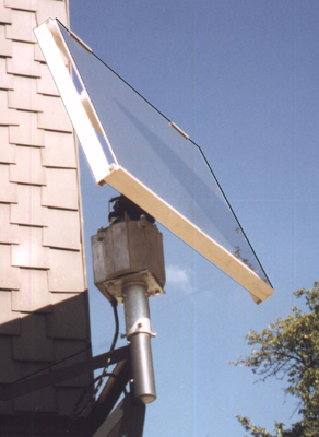
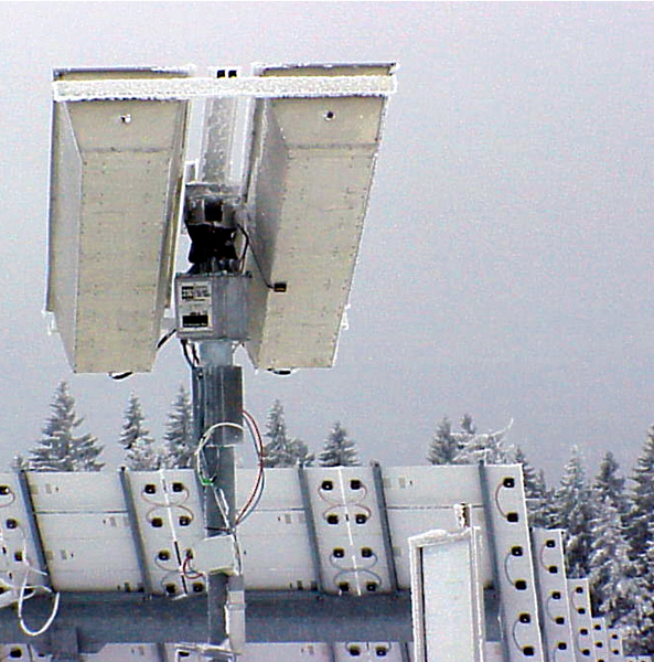
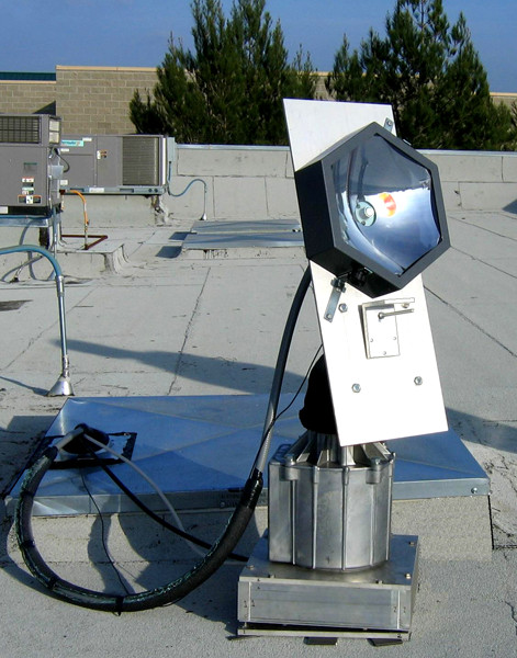
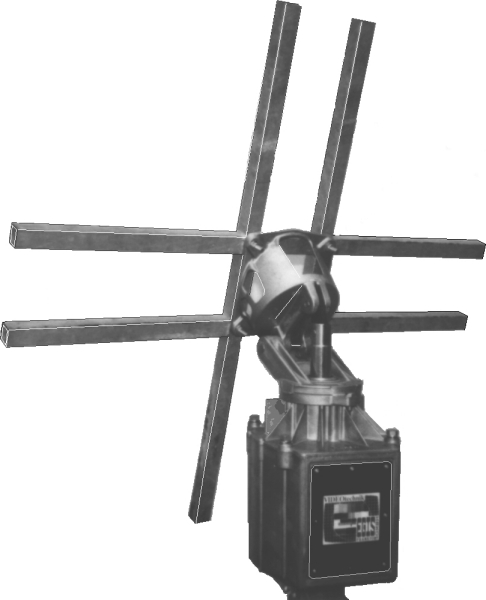
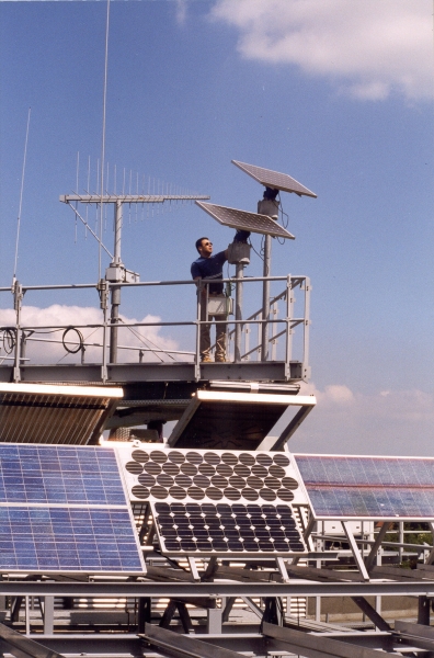
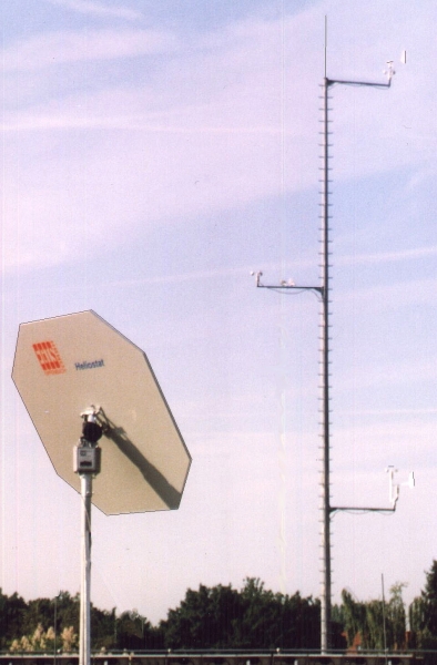
The azimuth-elevation turning system consists out of the rotor outdoor unit EPR203X as well as out of the indoor unit EPS103X. There are no additional parts necessary between "mast-holders" and "panel/reflector".

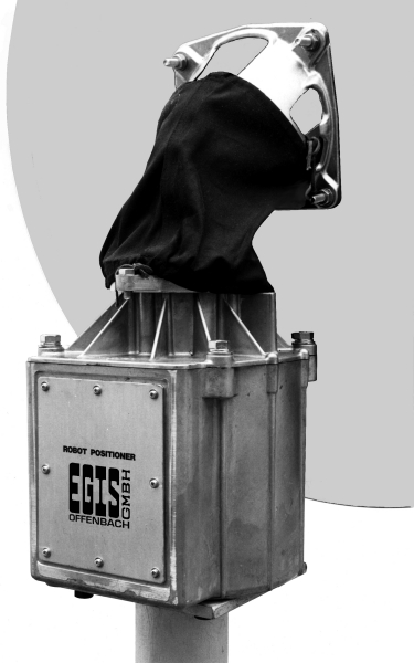
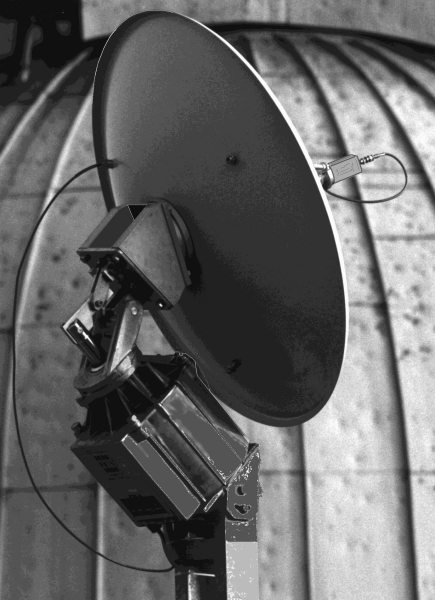
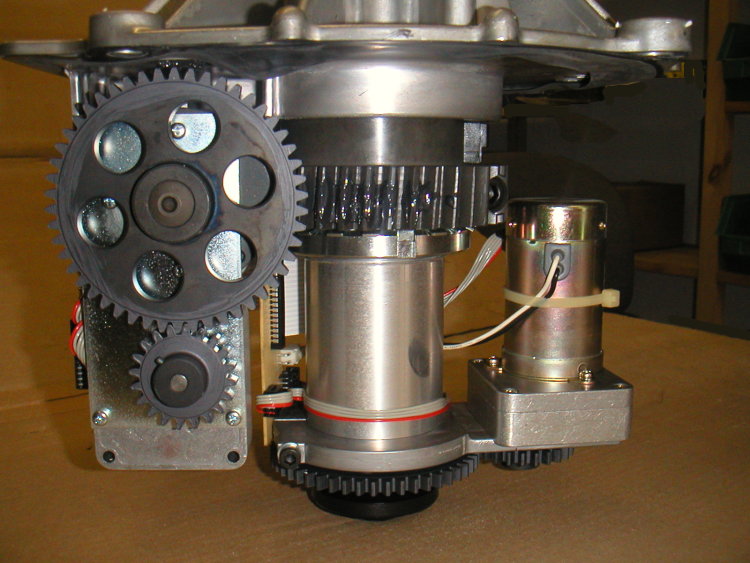
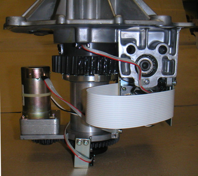
The rotor outdoor unit moves the object to be positioned fully automatically and microprocessor controlled on single positions or on tracks. For this in the rotor-outside-part, made out of a weatherproof aluminum pressure die cast, two separate 24 volts motors are installed.
These drive, using corresponding mechanism, the reflector with a high precision and return-accuracy of 0.3° into the wished directions, that is done as well as in azimuth as also in elevation direction.
Due to the two completely separated drive motors there is no need of immediate calibrating each mechanical tracking path and by that the former necessary exact calibrations so as very time-extensively set-up works of azimuth, elevations, north-south-axis etc. can be done comfortably at the control box!

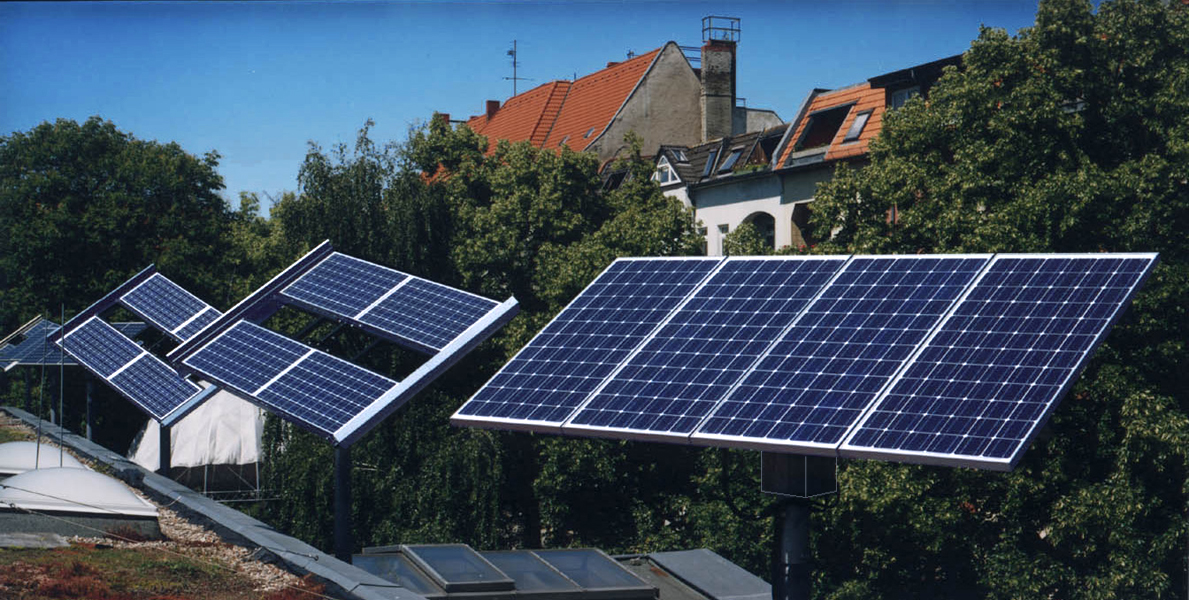
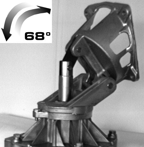
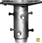
The u. m. azimuth elevation turning system moves, in standard-version, the objects in a 180° azimuth area. In elevation range the system suffers an elevation of 68°. Where exactly this lifting is used is up to the user: if elevation angle 0° until 68° or 25° until 90°. The system is doing this all very quietly and therefore, in contrast to many a wailing actuator motors, without boring the neighbors, naturally expectable at such a system.

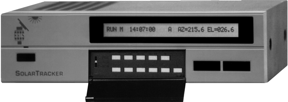
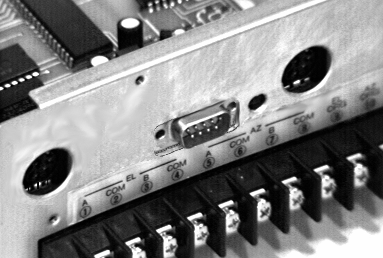
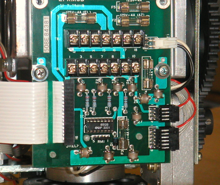
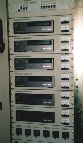
The only adjustment during montage and installation of the rotor-outside-unit is rough northern-south-alignment of the alu die cast housing. Therefore only rough because all eventually needed corrections can be done at the indoor unit. Consequently we have arrived now the technology of the operation and control unit. This is to be understood as a switching and computing center, the heart of the plant. The heart consists out of a quick 8-bit-microcontroller and allows the technicians under the users a real eldorado of programming. Already the assembler will be informed of incorrect or missing connections. So the control box contains e.g. an electronic blocking and overload protection, run direction supervision and related clear-text-information.
Now we come to the spots, that are of interest for the operators and users of the system particularly. There is e.g. the memory: all data and also the operational-program is accommodated in read only memory imprescriptibly.
To manage simple and easy tracking out of the data in the computer-memory only two technical instructions are to implement into calculations, namely the last unknown, that the system could not predict:
The location-coordinates of the rotor and time with date! After input of these values into the processor by means of keyboard the processor calculates the necessary azimuth and elevation angle of lineup-spot to each sun position in shortest time.
After this computing process you may start the tracking. Due to mechanical montage errors you will aim more or less exact at the sun. However for this rotor deviations are no problem: with resp. keys meet directly the sun, all comfortable out of your armchair!

This correction causes the control computer to save the data of the now exactly gotten sun position and the previously already entered data for later use. Immediately after that you may switch to "RUN" and the rotor will track in good quality.

Comfortably and simple - is installation. However – how behaves the system in everyday-business? Via front keys of the control box comfortably correct east-west-deviations. Or you take full control over the whole system via the key field.
The comfort doesn't cease, it has now just begun. The computer is able, thanks to his future-safe construction, to respect all locations no matter if western or eastern of Greenwich, northern or southern from equator. The u. m. calculations will be done always with the same accuracy. The rotor computer will calculate for each position on the earth in which angles the sun presently is to be expected!

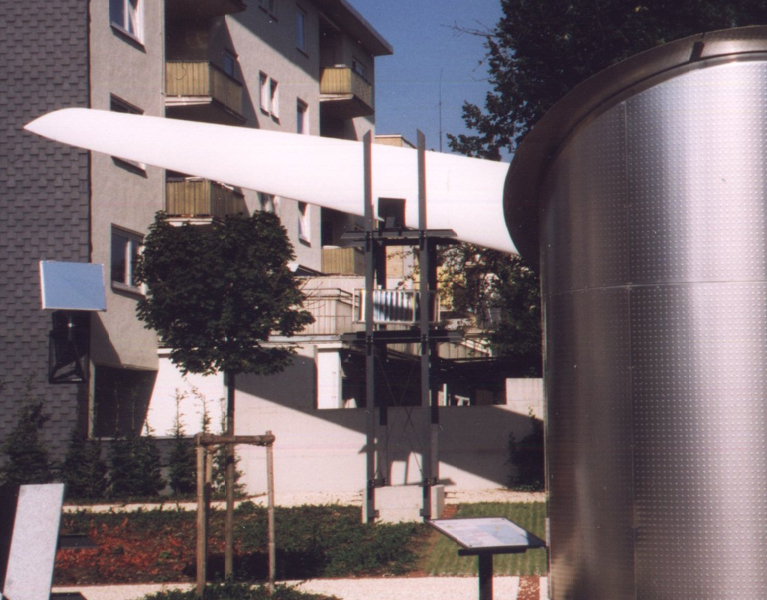
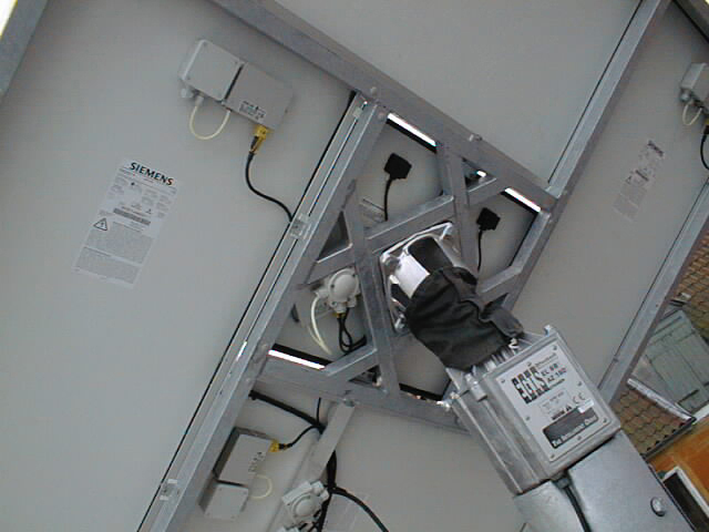
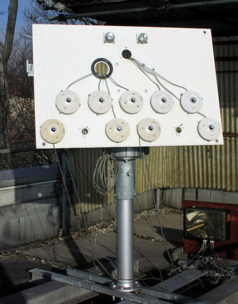
One of the most outstanding performance features of the system is its ability to cope with high wind speeds. Proved by Finite elements calculation for material and shape of the load carriing parts. You will recognize immediately the high durability and stiffness of the rotor aluminum-casing. However – how does it look indoors? Here some information for the technician belonging the construction of the rotor:


  • All used tooth-wheels are made out of steel not out of plastics!
  • All used tooth-wheels are mill cut!
  • The most important tooth-wheels are specially sediment hardened!
  • The drift gear for the AZ-movement weighs 2 kg all alone. Module 4 is used!
  • Used bearings:
    2 items ball-bearings: 110 mm Ø x 70 mm Ø x 20 mm
    4 items cone-role-bearings: 55 mm Ø x 30 mm Ø x 18 mm
  • All mechanism-parts are selected for long lifetime and high accuracy.
  • All parts – also in the rotor inside – have high corrosion-protection!
  • As motor feedback sensors neither mechanical switches are used – nor reed-contacts. – Only touchfree working twin-pulse probes (hall sensors) are used.
  • All feedback-signals of the rotor are not, as far spread, in 5 V transistor-transistor logic level. Signals to control box are amplified and only transferred faultless in 24 V format!
  • As lightning-protection and against net-phase-errors in the plant 10 voltage surge arresters are inserted (Will you find that at any ordinary motor?).

Kugellager

bearings

Apart of this – now see here the different "nice trifles":

  • LCD-display (40 digits/one line)
  • true angle-readings for AZ + EL
  • electronic mechanism-tolerance balance
  • motor delay to-sprint
  • selectable positioning-tolerance
  • determination of fine step size
  • determination of motor wait-state-time before new positioning
  • automatic system-test
  • passwords for system inputs
    and more and more…
Please read this more detailed in the English written setup/operation manual enclosed this positioning system.

It gets particularly interesting with the extended versions:

  • analog-signal dependent (input voltage dependent) fine-positioning and tracking
  • 360° azimuth turn range (endless turnaround)
  • 90° elevation span (horizon to zenith)
  • data interface to PC, modem or printer (RS 232 C)
  • solid state relais
  • GPS (Global-Positioning-System)-Software-Interface (NMEA183)
  • controlled (SERVO) drive speed
  • professional 19"-rack versions
and further versions and features are in progress.


Photo 170 Photo 171 Photo 172
gear parts inside rotor housing rotor terminal board


SPECIFICATIONS back to the beginning


OPERATIONAL COMPUTER:   EPS-103 mod. Solar
power supply 223/115 Volt AC or
24 Volt DC
consumption 16 VA Standby; max. 130 VA or
7.5 VA Standby; max. 80 VA
display and information LCD-Diplay
programmable memories 64 KB RAM
motor-supply-voltage 24 Volt DC
internal resolution: azimuth 0,0100°/pulse
elevation 0,0025°/pulse *
analogous signal range 0.2 to 12 volt DC > 100 kOhm
analogous input clock rate/resolution about 250 Hz
dimensions 300 mm x 80 mm, depth of 200 mm
weight 4 kg
carton-package (L x W x H) 39 x 29 x 15 cm
temperature limits: operational –5 °C to +40 °C
survive & storage –15 °C to +60 °C


ROTOR:   EPSR-203 mod.
special attributes 2 separate motors for azimuth and elevation-movements
motor voltage 24 Volt DC
power supply consumption max. 20 watts
'control device to rotor' cable 10 x 0,6 mm2 geschirmt (telephone cable proven!)
At version "SolarTracker Pro" these 10 wires are individually shielded.
4 x 1,0 mm2 (for motor power supply)
at lengths over 50 m 1.5 mm2
control-type actuation spindles and teeth gears
max. azimuth turn range 360° *
max. elevation range 90° *
return accuracy (part load): 0,3° (version with 68° EL)
In end positions of movement-lifting greater deviations may appear.
tracking resolution > 0.2° *
speed: azimuth approx. 4°/sec.
elevation 68° version: approx. 2°/sec. or 7°/sec. *
usable payload approx. 50 – max. 85 kg * (exc. 50 kg counter balance is needed)
casing alu, pressure-casting, weather-constant
dimensions: diameter approx. 318 mm
height approx. 625 mm
Click here to see a dimension sketching!
weight 27 – 33 kg *
carton package (L x W x H) 75 x 34 x 41 cm
mechanical connections: reflector see sketching
mast flat = approx. 240 mm Ø with 4 threads (screws delivery included)
max. reflector size 3 up to 6 m2 *
max. wind speed 62 km/h in operation,
up to 160 km/h belonging on panel size and static load
90° version: restriction to 50 % of reflector area and wind-/pay load! (strength proof)
temperature limits: operational –20 °C to +65 °C
survive & storage –30 °C to +65 °C


*  =  according to version


Some figures for 24 V stand-alone & accu operation:
  • standby dissipation beginning at 130 mA *
  • dissipation peaking 2.5 A for 0.5 sec. at high load & mass
* = according to version


PRICE LIST back to the beginning


VERSION | (excl. VAT) EURO
SolarTracker rotor incl. control box AZ 180° / EL 68° 2 298.00
version: standard/AC 230/115 V AC (effective power dissipation 13 W)
  or
version: standard/DC 24 V
SolarTracker Pro as above, however with solid-state relais 3 298.00


OPTIONS | (excl. VAT) EURO
DC 12 V 12 V power supply for version DC 24 V 478.35
Analog-Input analogous signal-dependent positioning load/power dependent 748.00
Data-Interface interface (RS 232 C) 798.00
GPS-Capture GPS-Software-Interface 549.00
is only supplied in combination with Data-Interface
MotionControl speed control and regulation for SolarTracker Pro only 989.00
GR-19 mounting of the SolarTracker Pro control electronics in 19" casing (2 HE, incl. illum. display) (image H) 998.00
AZ360 expansion on 360° azimuth turn-area 798.00
Masttop/Rotor Table 89 mm Ø (3.5") mechanical interface between rotor and mast (max. 89 mm Ø) 198.00
Masttop/Rotor Table 128 mm Ø (5.0") as above, however for max. 128 mm Ø mast 298.00
incl. mounting material (image E)
Panel holder universal connecting adapter between panel/reflector and rotor-head 298.00
Hot-dip galvanized, steel square tube (50 x 30 x 2 mm). Length 1 m. Connection material included in delivery (example applications/image Z).
Light direction finding tube for the easy and comfortable finding of the direction/position with the maximum of light 378.00
Wi-S1 wind-speed-sensor/shell-anemometer 317.35


All customers that are interested in advanced versions we offer a special service: now order the basic version and get the expansions immediately after availability (advice to soft- and hardware expansions). By that we secure that no financial and no functional decrease occurs on later deliveries!


Please tell us about your particular special application!


Technical improvements are subject of change!


      CONTENT:   versions | extensions/options | system description | specifications | price list     
      IMAGES:   controls and connectors | gear parts and options ||   MORE IMAGES AND INFO       


EGIS Cloud


EGIS-Logo E       G       I       S
EQUIPMENT GESELLSCHAFT für
INTERN. ELEKTRONIK SYSTEME GmbH
Flutstraße 34 – 36
D–63071 OFFENBACH/MAIN
Tel.: 069 / 85 83 27
Fax: 069 / 85 78 63
<< Homepage 20 minutes from Airport Frankfurt – 20 minutes to Frankfurt City E-Mail: Solar@egis.eu
Top